Modelling in Mujoco's XML format
Oh hello!👋
Welcome to this article on modelling in MuJoCo. Hopefully, this article will provide you with a good understanding of modelling in XML format, so that you may create many more complex models of your own.
I will demonstrate this by creating a Quadrotor in Mujoco which requires the use of actuators and sensors beyond bodies and geoms. I encourage you to open this XML reference document alongside this article. If you feel the need to read more about the syntax of the commands in use, then it will help a lot.
Let’s start by defining mujoco model. Use the model parameter for naming your model.
The rest of the elements will be placed inside this structure.
<mujoco model='quadrotor'>
    <!-- Body -->
</mujoco>
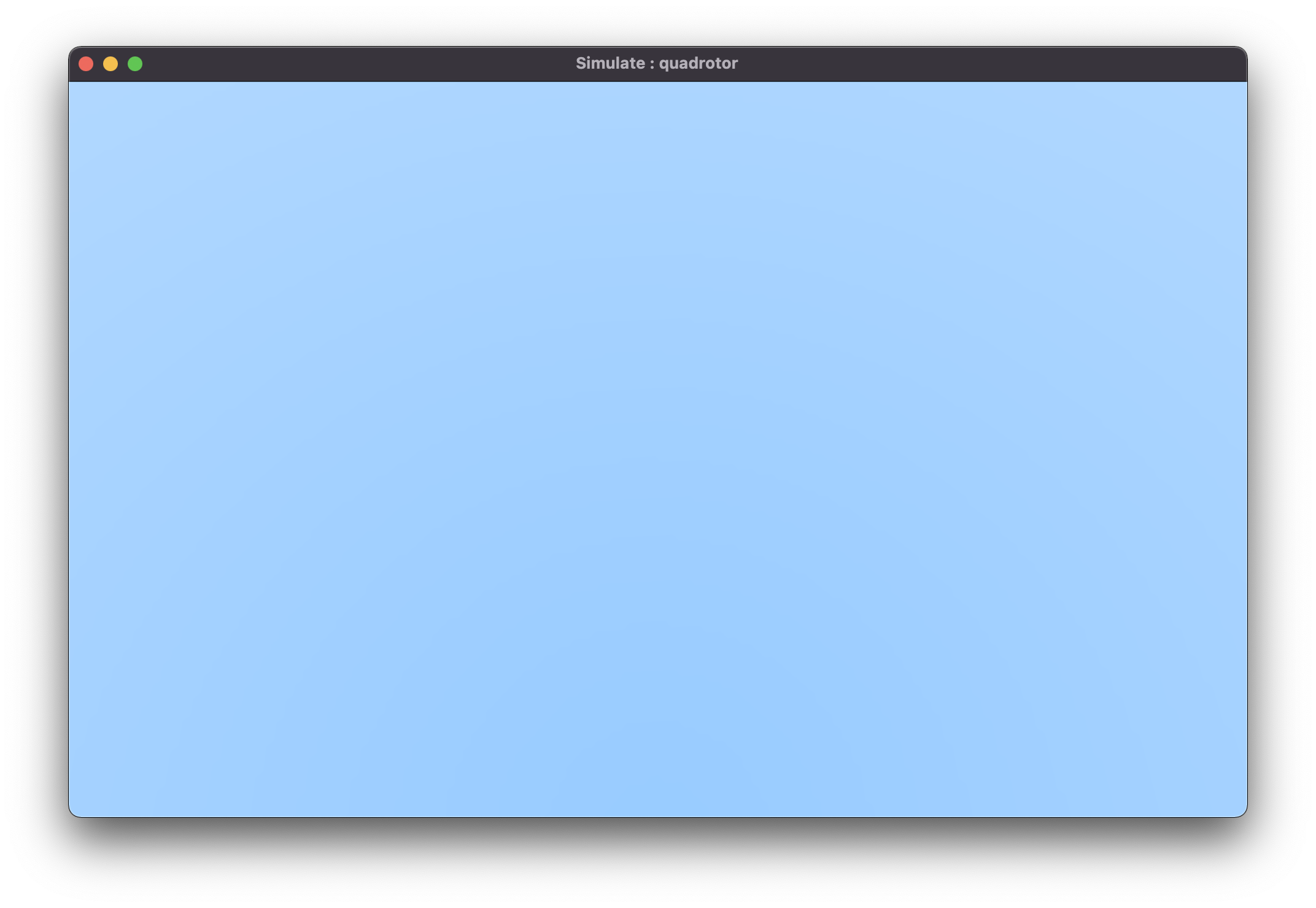
You will only see black background. We can change this by using asset command.
<mujoco model='quadrotor'>
    <asset>
        <texture type="skybox" builtin="gradient" rgb1="1 1 1"
            rgb2=".6 .8 1" width="256" height="256"/>
    </asset>
</mujoco>
Now, let’s create a floor. First we will create a worldbody, which acts as the parent to all others bodies. Every body or geom needs to be placed inside this tag.
<mujoco model='quadrotor'>
    <asset>
        <texture type="skybox" builtin="gradient" rgb1="1 1 1"
            rgb2=".6 .8 1" width="256" height="256"/>
    </asset>
    <worldbody>
        <geom name='floor' type='plane' size='5 5 .1' rgba='1 0 0 1'/>
    </worldbody>
</mujoco>
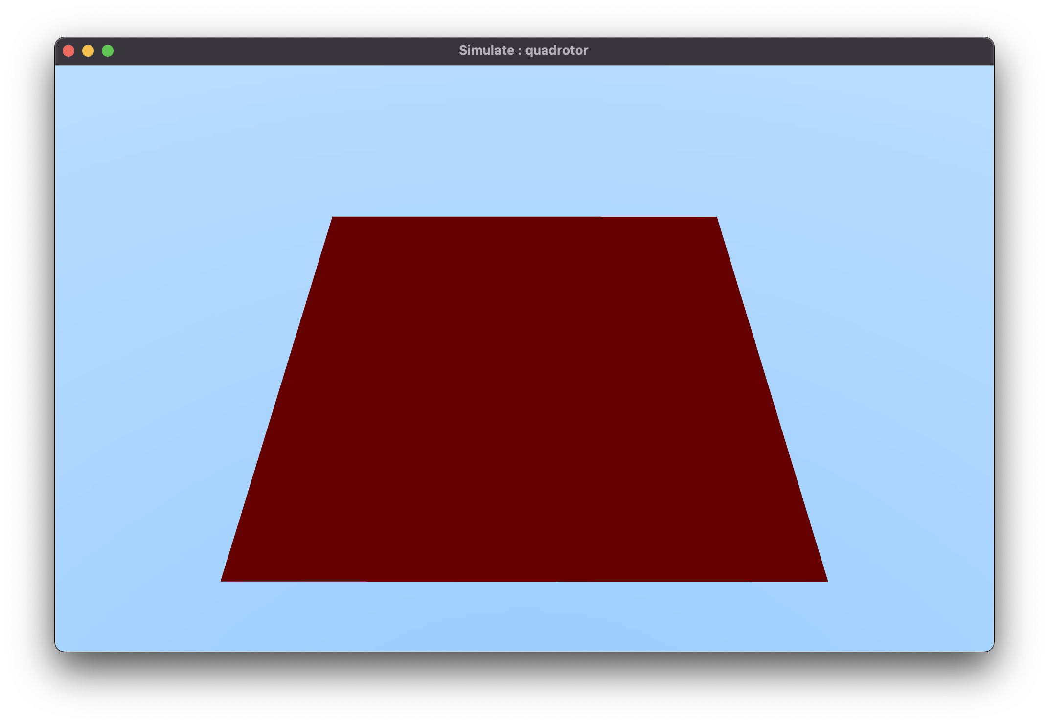
Geoms are used for collision calculation. The shape is chosen using the type parameter.
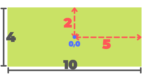
size gives the dimensions of the geom. You only specify the half values in size.
The values are of the form x y z. It spans both positive and negative axis equally.
The values 5 2 .1 means 5 in +x and 5 in -x direction. Similar for other axes as well.
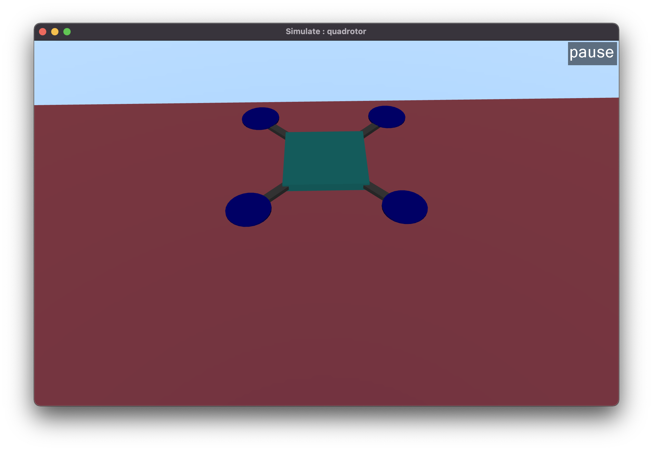
Next, we will design the quadrotor. Let’s start by defining the body. This will only create a box, nothing interesting.
<mujoco model='quadrotor'>
    <asset>
        <texture type="skybox" builtin="gradient" rgb1="1 1 1"
            rgb2=".6 .8 1" width="256" height="256"/>
    </asset>
    <worldbody>
        <geom name='floor' type='plane' size='5 5 .1' rgba='1 0 0 1'/>
        <body pos='0 0 3' name='quad'>
            <joint type='free' pos='0 0 0'/>
            <geom name="quadbody" type="box" size=".1 .1 .01" mass="0.1" rgba=".2 .9 .9 1"/>
        </body>
    </worldbody>
</mujoco>
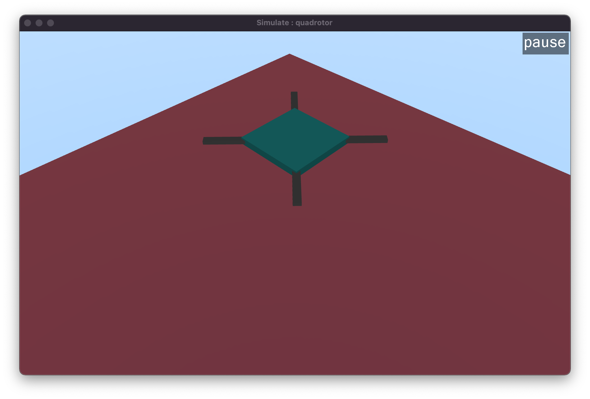
Remember, if you get confused which is x or y direction, then place the code below
to help yourself. Place this inside the worldbody. This will create three spheres
on the floor. Blue sphere shows the +x direction and Green shows the +y direction.
z axis is easier to understand. However, you can place another sphere for z axis.
Remember to use the site command and not geom.
<worldbody>
    <!-- This will help with coordinates -->
    <site name="origin" type="sphere" size=".1" rgba="0 0 0 1"/>
    <site name="posx" type="sphere" size=".1" pos=".2 0 0" rgba="0 0 1 1"/>
    <site name="posy" type="sphere" size=".1" pos="0 .2 0" rgba="0 1 0 1"/>
</worldbody>
Now we need to create the arms of the quadrotor. These arms will hold the rotors.
We need to use the euler parameter of the body to rotate the objects. You may
even use the quat parameter to specify the quaternion. I found euler easier to use.
To use euler, we need to specify three values x y z, each corresponding to
the rotation about x, y and z axis respectively. In this example, we will
set the x and y values to 0, since we only need to rotate the arm about the
z-axis.
...
<body pos='0 0 3' name='quad'>
    <joint type='free' pos='0 0 0'/>
    <geom name="quadbody" type="box" size=".1 .1 .01" mass="0.1" rgba=".2 .9 .9 1"/>
    <body pos=".1 .1 0" name="quadarm1" euler="0 0 45">
        <geom name="arm1" type="box" pos="0 0 0" size=".1 .01 .005" mass=".01"/>
    </body>
    <body pos="-0.1 .1 0" name="quadarm2" euler="0 0 -45">
        <geom name="arm2" type="box" pos="0 0 0" size=".1 .01 .005" mass=".01"/>
    </body>
    <body pos="-0.1 -0.1 0" name="quadarm3" euler="0 0 45">
        <geom name="arm3" type="box" pos="0 0 0" size=".1 .01 .005" mass=".01"/>
    </body>
    <body pos=".1 -0.1 0" name="quadarm4" euler="0 0 -45">
        <geom name="arm4" type="box" pos="0 0 0" size=".1 .01 .005" mass=".01"/>
    </body>
</body>
...
Now that we have the body ready, let’s define the rotors. The rotor definition requires the following steps:
- Using
geomto define the shape of the rotor - Using
siteto define the place of the rotor - Using
actuatorto place the rotor at the previously definedsite.
site does not take part in collision calculation, so even though it does look like a geom object its functioning is different.
The code section below only shows the rotor definition for one quadarm. You may figure out the rest on your own or find the complete code here.
...
<body pos=".1 .1 0" name="quadarm1" euler="0 0 45">
    <geom name="arm1" type="box" pos="0 0 0" size=".1 .01 .005" mass=".01"/>
    <geom name="rotor1" type="cylinder" pos=".1 .0 0.005" size=".05 .002" rgba="0 0 1 1" mass="0.0025"/>
    <site name="motor1" type="cylinder" pos=".1 .0 0" size=".05 .002" rgba="0 0 0 0"/>
</body>
...
Now that we have defined the site, we need to define the actuators and assign them to sites. Otherwise,
the rotors won’t perform as intended. Furthermore, actuators are defined outside the worldbody.
...
<actuator>
    <motor ctrllimited="true" ctrlrange="0.0 1.0" gear="0 0. 1. 0. 0. -0.1" site="motor1"/>
    <motor ctrllimited="true" ctrlrange="0.0 1.0" gear="0 0. 1. 0. 0. 0.1" site="motor2"/>
    <motor ctrllimited="true" ctrlrange="0.0 1.0" gear="0 0. 1. 0. 0. -0.1" site="motor3"/>
    <motor ctrllimited="true" ctrlrange="0.0 1.0" gear="0 0. 1. 0. 0. 0.1" site="motor4"/>
</actuator>
...
The model is ready and can be simulated. Here are the actuator control settings applied to the rotors. The current values will mean the quadrotor will perform a slow descent.
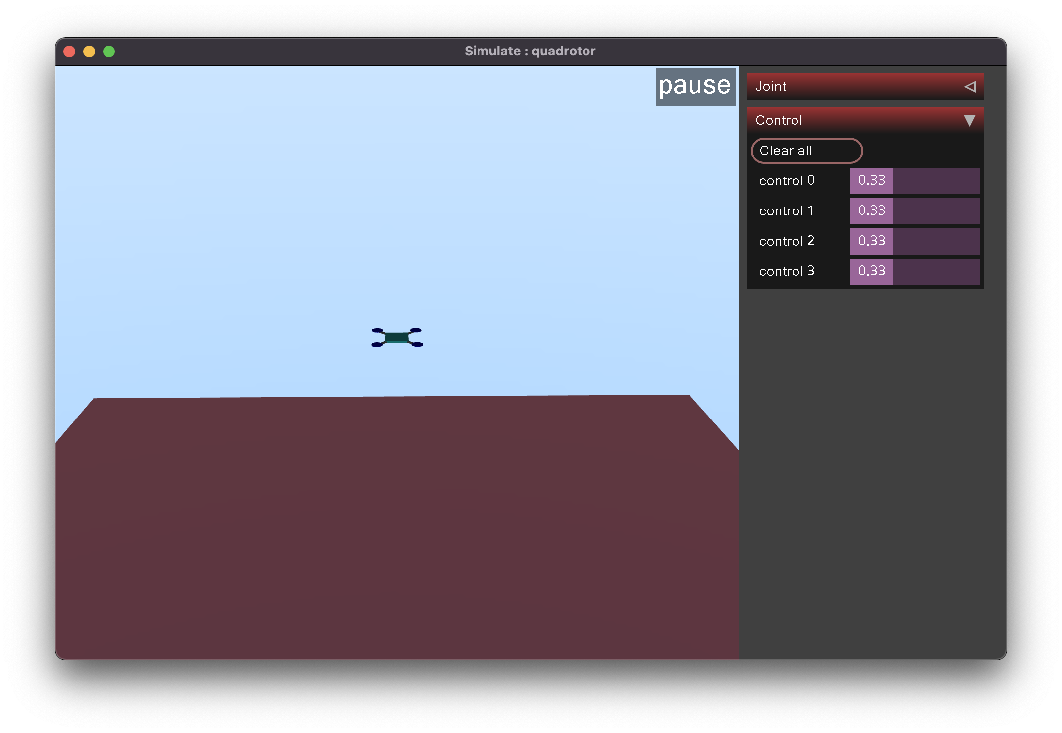
If the above video does not work then check it out here.
Phew! That was a lot. Hope this article helped you. The complete code is available on GitHub.